Beiträge von BuzzBazz

    Es ist eine Alternative für die nicht so geübten Bastler unter uns, die nicht löten können und dann evtl. die schlechten Eckverbinder einsetzen.

    Wenn man sich selber 'Lampen' für Ambilight bauen möchte könnte ich mir das auch manchmal vorstellen den Stripe zu verwenden.

    Der Preisunterschied bei SK6812 RGBW ist etwa 60€ zu 90€ bei 60 LED/m 5V.

    I agree. It is a more useful option for the less skilled as well. Forgive my previous comment that it would only be for the rich and "stupid", it would of course also be for the ones that don't know or want to deal with soldering.
    So one pays more for "less" work.
    If one places the strip directly on the back of the monitor/TV/whatever, and/or on a flat frame, this would be a option to just buy a long enough roll to cover the area one want's, then it would make the job easier.

    I noticed at link provided it said
    This plugin does not work for Kodi running on Raspberry Pi. There is an outstanding Kodi fix for that.

    Bummer about kodo on pi but is there any way for similar functionality?


    For the life of me I couldn't figure out how to edit my post.

    What I am looking for is a way for hyperion to only be active during a video. Not in menu or paused.
    My current setup is a pi4 running LibreElec. Years ago when hyperion was young I did manage to do this.


    Not sure if you got this fixed or not, but you could change the settings for where hyperion grabs information from the picture. I did this for my grabbers as they produce a static color bars image when no signal is on, but that images also includes a pure black segment on the right side, so I changed "Signal VMin/VMax & HMin/HMax" to 0.1, 0.9 & 0.92, 0.99. (if you enable the preview windows and display live video you should see a black border move around as you mess with the numbers.
    If you have an area in the menus that is pretty much always black it works surprisingly well. Still captures the video properly when there is dark scenes with light on the other side, but it's not foolproof.

    Looking at the pictures you have provided I can't seem to find R12 like on @blaisebarrette's. So there is no "easy" fix for you, but you could do the same as I did to solve it. I have found out that with my potato fingers I cut some slices of Kapton tape and "isolated" pin 13 before soldering to it. I tried to do it freehand without tape at first, and just some marker on the pins that were not 13, and that made a giant mess. If you have some Kapton, use that, if not, order a roll off the web, or ask some friends/local shops if they have some scraps for you. you only need 4 small pieces, so it's not a lot, but it does help with soldering the correct pin. Use a toothpick or a plastic spudger to help make sure the tape is properly applied to the pins so solder shouldn't leak/bleed over on the wrong ones.

    Hope that helps.


    Or get the two breakout boards, solder pin 13 on each (either with a cable or pins to add a cable) and done.

    Thank you for the kind words😀 I thought I'd make it as "plug&pay" for as many as possible if they want to copy the setup👍 Please look away from some of the words not having all the letters as I only proof read a few times with a slightly broken keyboard😅
    And thank you for the product you have made available for us to create awesome things with🙌

    [UPDATE 09.08.2023]
    CEC only requires HDMI PIN 13[CEC] and PIN 17[CEC/DDC GROUND]!
    Some CaptureCards/Video Loops/Grabbers have one or none of the pins connected internally!
    Depending on your soldering skill, the HDMI Breakout boards in my build are the simples solution to the problem.
    Order the boards with pins populated and use any jumper wire to connect PIN 13 & 17.
    For the CC/VL size I chose, "standard length" DuPont wire loom from things like a Arduino kit will work.
    Anything else, go wild.

    Reminder: CEC isn't really a thing to worry about if you are using a PC/Laptop as your source. There are boxes/fixes for that out there.
    but CEC is more "baked in" into set-top boxes, optical media and game consoles. (Nintendo Switch is a pain though. It does not turn off when you "turn off", it goes into standby and won't CEC off the display. At least not any of mine.)

    blaisebarrette , Yeah I can see how I’d confuse myself there😅
    I took it apart, took pictures and removed 3 cables (Pins 14[HEAC-], 18[5V] & 19[HEAC+/Hotplug detect]).
    At least we now know that pin 13 &17 are the ONLY needed in/outputs for the end devices to communicate the CEC signals.

    This is how it's been set up for the time being, now minus the 3 cables that where not needed. But yes, the boards are basically a "exploded view" for running things like a oscilloscope or other things. It really makes it a lot easier than soldering this:

    Mainly for the people that don't have access to this kind of tiny soldering and are "stuck" with this CaptureCard/Video Loop.
    As you can see from the horrendous soldering/cable job It was a pain to get just that one soldered to the right pin to start with, and to add a second cable I would need a great day with lots of positive influence to mentally take on😅😂 But I can confirm that on both of the CC/VL's I own, pins 13 & 17 are not connected (mainly because I've multimetered both ends of the internal try on p13 and it alone does not work😑)

    I’m running my H.NG on a Xbox series X and the wife’s setup is on the media PC (I have not found a 2 port HDMI switch with a remote yet, only 3+ ports get that.) On her setup we get around the CEC problem from the PC by just having her Xbox regain control over the TV and power on and off through that as it is connected directly to the TV. (at least until I find said 2port switch with ir remote.)

    For the rainbow no signal issue I got round it by doing this inside the web interface.

    I did have a little rainbow in the start, but after I changed the "Signal Counter Threshold" to 10 it updated fast enough to not give any rainbow. The thing is that on her "older" setup we're running 2.0.0-alpha.8, and one major loss there is that it does not show a guide where the signal detection area is, so I had no real idea what I was doing, but with mine I'm running the latest build and can see where and how big the box is. Once I had the numbers on mine I just copied them over and suddenly it worked on her setup as well. I set it there because the no signal image has pure black on that side, so as long as the rest of the signal stays static, it seems to update the lights to stay off. I tried to set the screen saver to be just black, but the rainbow would overwrite that every time, until now, with these settings. It isn't the best solution, but it makes all the difference compared to what we did before with having to manually swap between a instance of black and the CC/VL.
    That got tedious, fast.


    Oh god shoot me!🤯🤣😂😑😑😑
    I see what I've done wrong😑😑😑😑
    I have no idea how I've messed this up so damn bad. I even plugged probes into male to male plugs I have laying around to avoid making this mistake, and I still made the mistake!🤯🤯
    Mike72 and ghostface had it fixed, because of correct pin. I have no idea how I messed this up so bad because looking at the pins on my breakout boards I see what I did wrong.


    So, I finally figured out and fixed my setup!

    So far for the past year+ we have been running A rPi0 on my wifes TV with no real problems (some delay on the image used to render color, but no more than a few frames.)
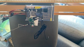
    Made a two frame solution (inner thicker frame for sturdyness and possible VESA mounting, and 3D printed brackets with custom locking angels for the thinner outer frame. Wanted to spread the light more than just 90degrees on a pure white wall.) and just cobbled the electronics as “nicely” as possible.


    Well, this summer we upgraded both TV’s (46” Samsungs with the “glass” border) and I thought I’d have a go at redoing the layout for the electronics. For a short time there I even thought I could “steal” 5V power from the HDMi cables and use the zombie power for something.
    DO NOT DO MY MISTAKE! It just made the capture card/rPi’s go crazy because it wasn’t stable enough😅

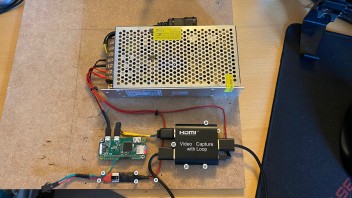
    But, this was my “final” setup.

    I bought male to female chuko power cables, stripped and soldered the female plugs before zipping them to the powerbrick.
    I wanted a cleaner way of transporting the box with as little cables hanging off it as possible.

    Capture card and rPi run off the same connector on the PSU with self made USB Micro cables. Costed almost nothing on Ali.

    Added a photosensor switch as a test on the rPi0 setup to see if it could handle the power, and it works like a charm.
    If anything goes down, swipe your hand over the top of the TV to kill the lights🙌🏻👍🏼😅
    A handy backup just in case, say I finally make one for my mom😅


    But I found a new problem.

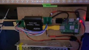
    CEC does not work with all capture cards!😣☹️

    So, I found the pinouts inside the capture card and soldered the CEC pin to no avail, and instead of soldering more tiny pins I found these simple breakout boards on Ali.
    To err on the side of caution I added breadboard pins to pins 13,14,15,16,17,18 & 19.
    Found some dupont wires and added them to all pins.
    Had some problems with video not doing its job because of pin 15&16, so those got disconnected. I also don’t know how needed pin 14,18 & 19 are, but they don’t mess with audio or video so they got left there, and I fixed the damn CEC not working.
    I guess if I cared to solder the wires internally in the capture card it would work as well, but I do not have the tiny hands for that😅


    Aside from the HDMi cables, everything was cut, soldered and heatshrinked to custom lengths on my own, and aside from the “HDMi CEC bypass loom” there is very few cables to deal with.
    The setup with the rPi3 did look a little cleaner before the CEC fix was in place, but now I don’t have to use the remote for anything, so it’s a win-win for me😅

    Reused the 3D printed brackets to save time.

    We also got the Signal Detection to work by slamming the detect sector to the black side only (static "No-Images" on capture card ) and now the leds operate flawlessly on their own, no need to turn on or off manually🙌🏻

    Both setups are running 190 RGBW leds (60 top/bot & 35 sides) and aside from some super bright screens killing the power to the end-leds (the go orange, not enough juice), only one power input at the start was needed.


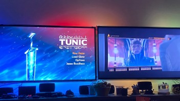
    Than you again Hyperion-Project for a great DIY tool! It really makes it look wonderful!


    I'll add this as a "as much complete" shopping list over the things I used. Most of them where from Ali, and helped ton.

    Tools:

    Center Punch (so helpful with holes): https://www.aliexpress.com/item/1005001890124731.html
    TS80 Soldering kit: https://www.aliexpress.com/item/4000629077876.html

    Soldering Wick: https://www.aliexpress.com/item/1005003472960106.html
    Solder wire: https://www.aliexpress.com/item/33008603722.html
    Solder cleaning "ball": https://www.aliexpress.com/item/1005001511833160.html
    Solder Flux: https://www.aliexpress.com/item/32948598235.html

    Parts:
    Raspberry Pi Zero w/Wifi and Pi 3A+ (I guess any Pi knockoff would be fine, I just bought two without wifi by accident, before ordering a wifi one and rPi3 Model A+ from local shops.)
    LEDS - SK6812 RGBCW, White PCB, 5m 60 IP65 - Similar WS2812B (I wanted these because of the extra Cool White channel, white PCB reflects more light, not too many LEDs per meter, and waterproofing for idiot control.): https://www.aliexpress.com/item/33022302220.html
    5V 30A PSU: https://www.aliexpress.com/item/33059722862.html
    Capture Card (Video loop): https://www.aliexpress.com/item/4001064519537.htm


    HDMi Breakout boards: https://www.aliexpress.com/item/1005004343592426.html

    Micro USB connectors: https://www.aliexpress.com/item/4000310713595.html
    4pin JST Connectors (I didn't order 3pin ones and just took out the extra pin/cable.): https://www.aliexpress.com/item/32982310944.html
    Red/Black Cables (10 meters for almost nothing): https://www.aliexpress.com/item/2019902170.html

    Crimp terminals: https://www.aliexpress.com/item/32985520928.html
    Random ass. Heatshrink tubes: https://www.aliexpress.com/item/32855524573.html


    Extras:
    Photosensor (seller has other types as well): https://www.aliexpress.com/item/33021060851.html
    6x dif. Color 2m 36AWG cables (for tiny soldering): https://www.aliexpress.com/item/1005003117658474.html
    C13 to C14 Power cable: Bought at a local electronics store. Could probably find something in a yard sale.
    DuPont/Jumper Wire loom and pins: Had laying around from an Arduino set I got a long time ago.

    MDF Hobby Board: From local store that used it for shipping packaging.
    Thin planks: Local hardware store.
    3D Printed Brackets: Designed self, way too overcomplicated, will make a better solution at some point.
    Random old USB cables I cut: Just random extras over time.

    All these things vary in price all the time, so I can't give an estimate on how much I've spent, factor in that I've bought some of the tools for other projects, and some other the parts have tons of stuff in them while I only used a few, and add the time it took me to design and print failures and "final" parts, solder the first revision, undo Rev1, place and trace Rev2...
    I wouldn't want to try and add up all the hours. Just the place and trace for Rev2 took about 2 days with testing and seeing what would work and not😅😑😂👍
    Modifying Rev2 to work with the rPi3A+ took about 30min with all labor😑😅

    This is definitively a hobby and a passion, but can be done simply and cheap if wanted. It comes down to what you have time for.
    I built this this way because I would like to make some rock solid platforms I can package and give as gifts to those around me, but for that to work, the "units" need to be "idiot proof", and the only way to find out is to try, and that is what I've done here.

    This is what worked well for me, so I'm listing all this because maybe it can help others👍🙌😊

    On my profile it states that I am Swedish. But I can’t find a way to change it. Is it based on IP or does it just pull location based on a broad area “pin”?
    I love in Norway (but am American)
    Can I change? If not, then it’s okay. I’ll just pretend it’s my wife’s account (She is Swedish)

    i have a suggestion> by any chance, did the PWM lite it up like full white? If you deselect PWM they go off again?


    i did the test myself on Hyperion.NG 2.08 , look at remote control and switch of smoothing, with me that was fixing the led's not lit up.
    It looks like there's a bug in image softening ( smoothing) while it RUN's the led's don't do anything on SPI and WS2801.
    you can't turn it off in my build, button SAVE is unlit... only possible with remote control option.
    maybe this helps you, maybe not..
    anyway, i go back to my first build ( sd card) with Hyperion.NG Béta 1 which runs perfectly from the getgo.


    Selecting PWM just fixed everything for me. Everything is working. It shouldn't, but it does XD
    Only one thing I can't yet figure out: Boot animation will not work, so I disabled it and everything starts up fine. But when I power off the TV, the standby signal from the capture card has a lot of colors, is there a way to set it up so that it sets color to black or "off" when it sees a specific image for "xx" amount of seconds?

    *UPDATE*
    As I was taking a break and the wife wanted to understand what I had sunk 300$ into and no still no lights worked I had a breakthrough.
    Just as a test, I selected [RPi PWM - WS281x], as it was the last thing I have not tested and it should not work, but it's a ws281x library and I wanted to do something else to explain to the misses...


    the lights lit up...


    Selecting PWM, for WS281x leds, my SK6812RGBW leds, lit up.
    The leds I've been struggling to make work on SPI, the leds I've spent more money on after the first purchase, to make them "work", now work with PWM.


    Why do they not work with SPI and the way they are supposed to work? I wouldn't think setting up Hyperion should feel like doing a Remote Associates Test.

    Yo TPmodding! I have now followed your video and copied everything you said, but guess what? It did not work. It keeps spitting out an error about "no such file or directory". But following your video it should have worked, right?

    Code
    2020-11-03T17:41:55.918 hyperiond LEDDEVICE    : <ERROR> Device disabled, device 'sk6812spi' signals error: 'Failed to open device (/dev/spidev0.0). Error message: No such file or directory'


    The furthest I've gotten is the first LED to light up GREEN, but I think that was an accident as it also happened sometimes when I plugged the SP501 LED controller to the LEDs.
    Also, I seem to have hit a slight problem where the baudrate seems to be off. You even commented on it in a different thread:

    why is your rate 3000000?
    you sure your spi is working?
    https://www.raspberrypi.org/do…README.md#troubleshooting


    So I have doubled down in trying to figure it out but I can't find any logics to some of the things you say vs. some of the things you do.
    So please... I have done exactly like you got angry at me for not doing in the first place. All I am after is some understanding, maybe even a slight explanation.
    Are WS28xxSPI and SK6812SPI supposed to use the same library?
    And if so, why is their baudrate in Hyperion set to something beyond what it's specifics that Adafruit states?
    Is the settings in Hyperion not relevant to these two sets of LEDs?
    I have tried using both GPIO18(pin12, spi1 ce0) and GPIO9+10(pin19+21, spi0 MISO/MOSI) but not gotten any difference in the LEDs.
    Also, why is it stated in Hyperion that spidev0.0 and spidev0.1 are options, but I'm being told that there is only one SPI line, when the pi tells me there are two?
    And which is which? Is "spidev0.0" SPI0 or SPI1?

    SPI device is on diffrent GPIO's , you can see that on schematics. You are measuring on a input/output of the PI!! thats doesnt work, its not a SPI device/controller output'
    i think you need PIN 19/21/23 to make it work > combination of 19/23 or 21/23 > thats GPIO 9/10 and 11
    thats between a dataline and CLK line if you have 4 trails on the strip.


    Yeah I was going to ask, that would be if you are running a 4 pin LED strip.
    All I have is a 3 pin one.

    As for to clean stuff up a little, this is what my setup looks like.

    Only main difference is the Pi is a ZeroW.


    When googling I am told that I can not read the 3.3V from GPIO18 with a normal multimeter, but that I would need a Oscilloscope to be able to see it. I don't own that, but I agree that there might be a hardware issue.

    you know that the pin-out for a PI1/zero is really diffrent than what i have on RPI3. I used schematics from internet on PI forum and Hyperion to locate the pin-out. I don't know which GPIO it should be on a ZERO or PI1, you can find that really easy. but it seems that or; pinout is wrong/datasignals is mixed or; SPI device is NOT running or selected


    Googling shows me that RPi3, 4 and Zero/ZeroW all have the same 40pin layout. So it should be the same pins.


    RPI3 is much more powerfull than the first type, you can look that up yourself, especially with so much led's i would go for a device that has already build in HDMI functions so setup is easy. It only costs 45 euro/dollar so you spend that already anyway


    Yeah I get that, but as I was going to make this run I wasn't thinking of adding a bigger more expensive Pi to the mix.
    Having said that, the ZeroW came out in 2017, so it's not that old.
    Also, I'm not powering the 190 LED's off just the Pi. as far as I can figure out that would blow the tiny sucker when it's pulling close to 10Amps. But no worries, I am in hardware fix mode again to see if I can't figure out of this problem.
    Unless anyone has bumped into this problem with GPIO18 barely providing 0.0025V instead of 3.3V, I might look into buying another, newer Pi.


    some pinouts charts are really deceitful, they will count into normal numbers ( numbering on pcb) OR GPIO pinout numbers


    Oh... All I've been told was that the 40pins are supposed to be the same 40 pins for most devices. I'll do some digging.