Correct connection of the Level switch on the RPI4

  • I am using hyperyon.ng on my RPI4, but I have a problem, my APA102 LEDs blink randomly from time to time. I found information on this forum, this arises from the fact that the RPI GPIO pins give out 3.3 volts of voltage, and the APA102 LED strip accepts 5 volts. This can cause occasional outbreaks. I purchased a logic level converter like this to solve this problem
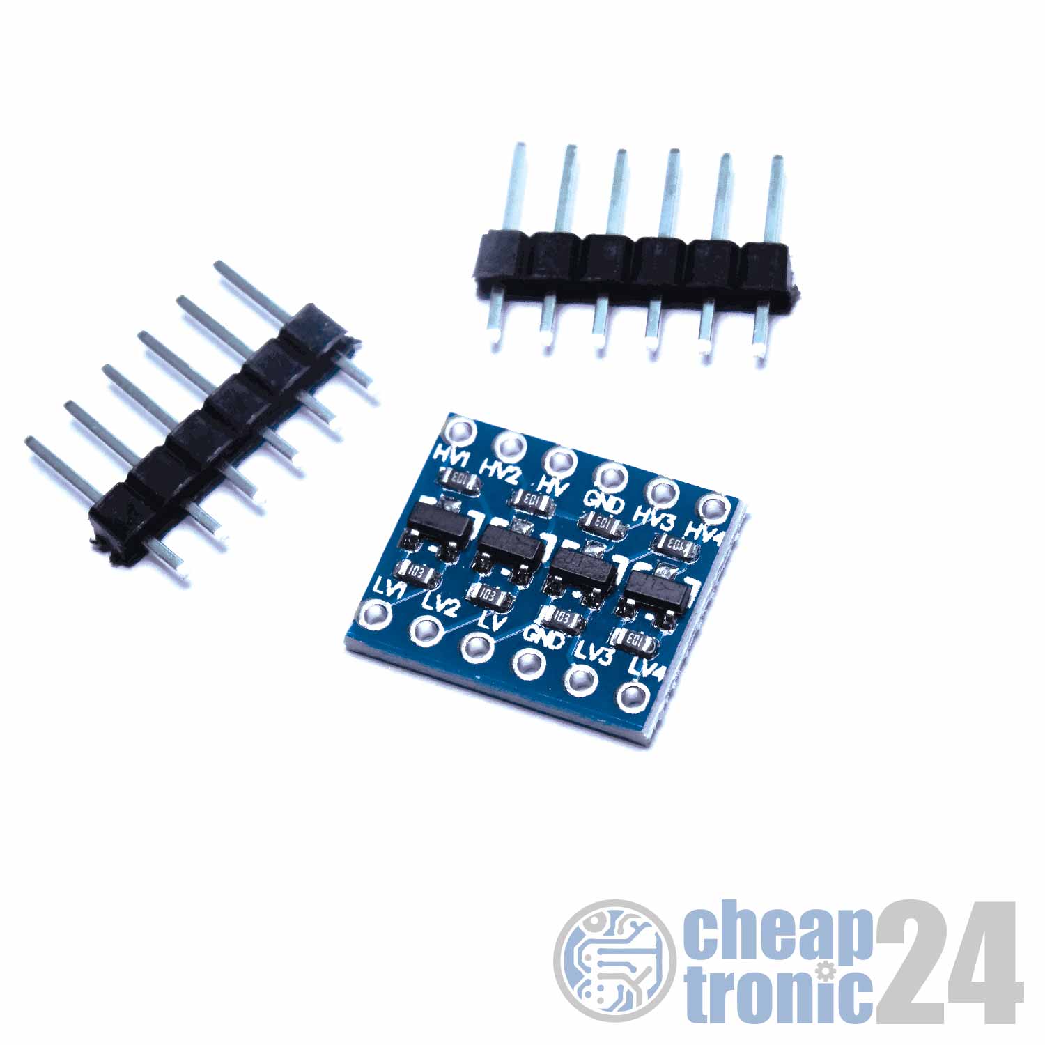
    But I could not figure out how I should connect it to the power circuit. Most of the pictures describing its connection assume that the RPI and the LED strip will have the same power supply, but I don't need that. I want the RPI to have its own USB power supply and not depend on the LED strip power supply. At the moment I have connections according to this scheme:


    I would like to ask you to draw a diagram of how I should connect a logic level converter to this circuit so that everything works correctly and I have 2 power supplies, separately for the RPI and for the LED strip. Thank you in advance for your help!

  • it doesnt matter where your 5v comes..., you can use a second psu for that, but as i said, it is only important to have a common ground


    At the moment, I have implemented a connection according to the following scheme:

    But, either I soldered something wrong, or this circuit is wrong. The LED strip is not working.


    I see that it differs from your circuit in that the 5 volt power to the HV pin is supplied from the power supply, and not from the Raspbeerry Pi. It is fundamentally?


    Do I understand correctly that my scheme should be like this?


  • Yes it works! Thank! I think this picture should be added to the wiki and the Raspberry Pi setup tutorial to close this issue permanently on this forum!


    And how did you have install hyperion on your rpi4? In the kodi addons section or by hypercon?

  • I've always installed hyperion via hypercon, but recently the rpi4 support has been removed from the installer.
    I slightly modified the installation script to pass the processor check and hyperion on rpi4 works fine for me.
    In the file https://github.com/hyperion-pr…r/bin/install_hyperion.sh
    replace the line

    Code
    CPU_RPI = `grep -m1 -c 'BCM2708 \ | BCM2709 \ | BCM2710 \ | BCM2835' / proc / cpuinfo`


    with

    Code
    CPU_RPI =` grep -m1 -c 'BCM2708 \ | BCM2709 \ | BCM2711 \ | BCM2835' / proc / cpuinfo`
  • Hi,


    I'm pretty new to this but I followed the wiring diagram TPmodding posted for using one PSU to power strip and Pi4 and I got hyperion working. One thing I like to understand though is what is the connection between PIN1 and PIN4 for? What does it do and is it actually required for this setup?


    Many thanks in advance!


    https://www.google.com/search?…w=1584&client=firefox-b-d


    at least you need one common ground connection between all psu

  • Hi,


    I'm pretty new to this but I followed the wiring diagram TPmodding posted for using one PSU to power strip and Pi4 and I got hyperion working. One thing I like to understand though is what is the connection between PIN1 and PIN4 for? What does it do and is it actually required for this setup?


    Many thanks in advance!


    This is completely unnecessary, it is enough to connect according to this scheme

  • Thanks a lot ReWiG. I much appreciate the quick response. PIN2 only seems to go into the level shifter but then nowhere from there. Is a wire missing in the diagram?


    Thanks


    This is completely unnecessary, it is enough to connect according to this scheme

  • Thanks a lot ReWiG. I much appreciate the quick response. PIN2 only seems to go into the level shifter but then nowhere from there. Is a wire missing in the diagram?


    Thanks


    Everything is as it should be

  • there's more ways then only one to connect a levelshifter wiring, mostly to boost from 3.3volts to 5 volts or you can use them vise versa.


    the important notice is to always use a common GND to the whole wiring, this way it doesn't matter if you use diffrent kind of DC voltages in your setup.
    the grounding will make it stable ( no flickering of the leds)


    You are just using channel in/out to boost either the Data or Clock. so A to A1, B to B1 ( can be diffrent each type of shifter) etcetera...
    Always feed this 2 signals seperately trough the levelshifter.

Jetzt mitmachen!

Sie haben noch kein Benutzerkonto auf unserer Seite? Registrieren Sie sich kostenlos und nehmen Sie an unserer Community teil!